
- Overview
- Launch Sites
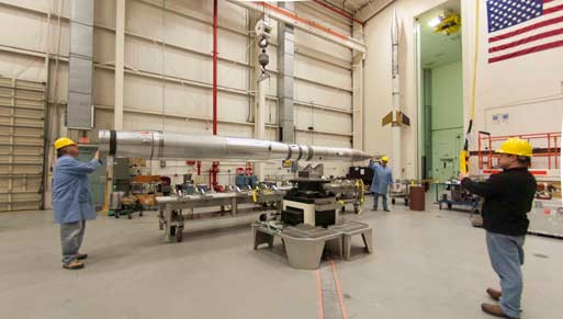
- Payload testing
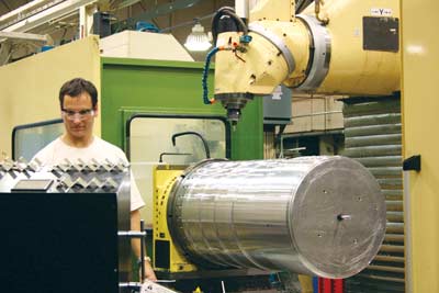
- Machine Shop
- Payload Systems
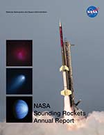
The Sounding Rockets Program Office (SRPO), located at NASA Goddard Space Flight Center's Wallops Flight Facility, provides suborbital launch vehicles, payload development, and field operations support to NASA and other government agencies. SRPO works closely with the Sounding Rocket User Community to provide launch opportunities facilitating a broad spectrum of science applications.
The Sounding Rockets Program supports the NASA Science Mission Directorate’s strategic vision and goals for Earth Science, Heliophysics and Astrophysics. The approximately 20 suborbital missions flown annually by the program provide researchers with unparalleled opportunities to build, test, and fly new instrument and sensor design concepts while simultaneously conducting worldclass scientific research. Operations are conducted from fixed launch sites such as Wallops Test Range (Virginia), Poker Flat Research Range (Alaska), and White Sands Missile Range (New Mexico) as well as sites such as Andoya Rocket Range (Norway) and Esrange (Sweden). Launch operations are also conducted from mobile sites set up by the Wallops Test Range. Mobile "campaigns" have been conducted from Australia, Puerto Rico, Brazil, and the Kwajalein Atoll. The mobile capability offered by the Wallops Test Range allows scientists to conduct their science "where it occurs". Coupled with a hands-on approach to instrument design, integration and flight, the short mission life-cycle helps ensure that the next generation of space scientists receive the training and experience necessary to move on to NASA’s larger, more complex space science missions. The cost structure and risk posture under which the program is managed stimulates innovation and technology maturation and enables rapid response to scientific events.
With the capability to fly higher than many low- Earth orbiting satellites and the ability to launch on demand, sounding rockets offer, in many instances, the only means to study specific scientific phenomena of interest to many researchers. Unlike instruments on board most orbital spacecraft or in ground-based observatories, sounding rockets can place instruments directly into regions where and when the science is occurring to enable direct, in-situ measurements. The mobile nature of the program enables researchers to conduct missions from strategic vantage points worldwide. Telescopes and spectrometers to study solar and astrophysics are flown on sounding rockets to collect unique science data and to test prototype instruments for future satellite missions. An important aspect of most satellite missions is calibration of the space-based sensors. Sounding rockets offer calibration and validation flights for many space missions, particularly solar observatories such as NASA’s latest probe, the Solar Dynamics Observatory (SDO), RHESSI, Hinode and SOHO.
World wide launch sites
Sounding rockets are launched world wide from both permanent and temporary launch ranges. Mouse over the map to get more information. Click on popup to visit the launch facility's home page or, in case of inactive or temporary launch site, other sources for more information. Purple dots indicate inactive sites and green dots indicate active sites.
- Poker Flat Research Range, AK
Poker Flat Research Range is located close to Fairbanks, Alaska. Missions studying the Aurora Borealis and other Sun-Earth connection phenomena are launched from Poker. - Greenland - Inactive launch site
Sounding rockets have been launched from two sites in Greenland - Sondre Stromfjord, now Kangurusulak and Thule. - Fort Churchill, Canada
Fort Churchill was used 1950's through 1970's to launch sounding rockets. - White Sands Missile Range, NM
White Sands Missile Range, NM is used for many sounding rocket missions carrying astrophysics and solar physics experiments and instruments. - Wallops Flight Facility, VA
NASA's Wallops Flight Facility is home of the sounding rockets program and includes a launch range on Wallops Island. - Camp Tortuguero, Puerto Rico
The last time sounding rockets were launched from Puerto Rico was the El Coqui campaign in 1992. Launches were coordinated with data from the Arecibo telescope facility. - Alcantara, Brazil
The last time sounding rockets were launched from Brazila campaignwith multiple launches in 1994. - Punta Lobos, Peru
The last time Punta Lobos was used for launching sounding rockets was in 1983 when 18 rockets were launched to study equatorial atmospheric and ionospheric phenomena. - Barking Sands, HI
Barking Sands, HI is mostly used for Department of Defense rockets, but has served as a sounding rocket launch site in the past. - Kwajalein Atoll, Marshall Islands
The Kwajalein Atoll in the Marshall Islands is an active launch sites and campaigns with multiple rockets have most recently been staged from Kwajalein in 2013. - Svaalbard, Norway
Svaalbard houses Norway's second sounding rocket launch range in addition to Andoya. - Andoya, Norway
Andoya in northern Norway is a very active permanent launch range used by both US and European researchers. Primary focus is on studying the norther lights or Aurora Borealis. - Esrange, Sweden
Esrange, Sweden is a permanent sounding rocket launch site and is used for Auroral studies. - Woomera, Australia
Sounding rockets were launched from Woomera Australia to study Supernova 1987A. Woomera has an established launch range with a relatively large land impact area.
List of active NASA sounding rocket launch sites:
Kwajalein Atoll, Marshall Islands
Future launches are planned from Woomera, Australia.
List of inactive NASA sounding rocket launch sites.
Note that these sites may be active launch ranges, but not used for NASA sounding rockets today:
The launch and flight phases of a sounding rocket mission are violent and stressful events for the scientific payload. The sum of the destructive elements to which such a payload is exposed is called the “payload environment.” A rigorous environmental test plan helps to ensure that a payload will survive this hostile environment and continue working well enough to successfully complete its mission.
Vibration Testing – Sine and Random
Click on image to play video.
The test specifications used for a particular payload are determined by the ignition and burn parameters of the motor vehicle configuration designated for that launch. Vibration tests are performed in three payload axes - thrust and two orthogonal laterals. There are two types of vibration inputs – sine and random – for each axis. A payload’s response to an input vibration depends on the size, weight distribution, and harmonic frequencies of the assembly. A test is considered successful when the payload continues to perform its functions as designed after each round of vibration.
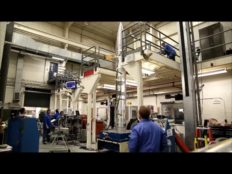
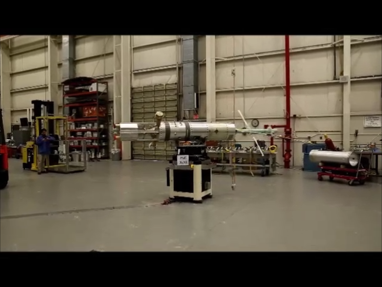
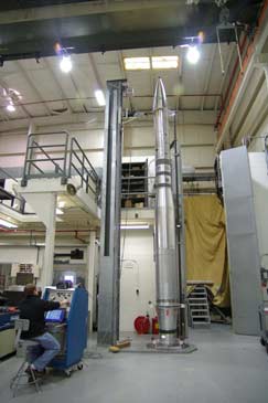
Bend Testing
All payloads are flexible to some extent. The pressure effects of high velocity atmospheric flight create bending moments along the length of a payload, with the maximum moment occurring at the base where the payload attaches to the motor. The severity of this moment and the resultant payload bending are predicted during a detailed performance analysis prior to testing. Most often the deflection is measured at the tip, to determine the sum of all joint deflections under the anticipated base moment. A test is considered successful if the total tip deflection is equal to or less than that predicted in the performance analysis, and if the deflection at an individual joint is within acceptable limits.
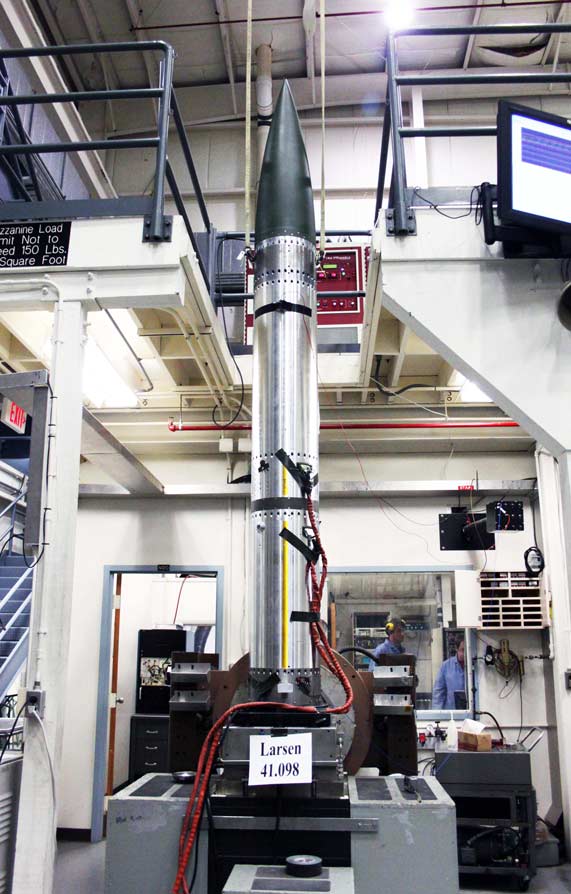
Spin Testing - Operational And Deployment
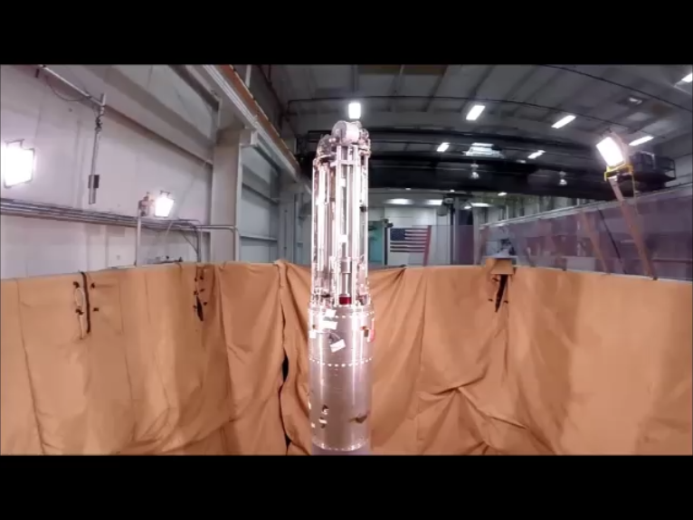
Click on image to play video.
Sounding rockets, like all ballistic missiles, are spin stabilized. Motor vehicle fin cants ensure that the assembly begins to spin-up as soon as it leaves the rail. The amount of spin at any given time in the flight sequence is referred to as the roll rate. Payloads often use the resultant centrifugal force to deploy doors, sensors, and other devices. Maximum spin rates, maximum rate gradients, and even the entire flight sequence rate profile can be reproduced in the spin test bay. Most spin deployments can be performed in this same facility and photo or video data can be collected. Using this optical data, in conjunction with telemetry signal data monitored during the tests, the payload team can verify that payload instruments are functioning properly throughout these events, and that the deployments can be performed successfully in flight, and/or they can discover problems which need to be addressed.
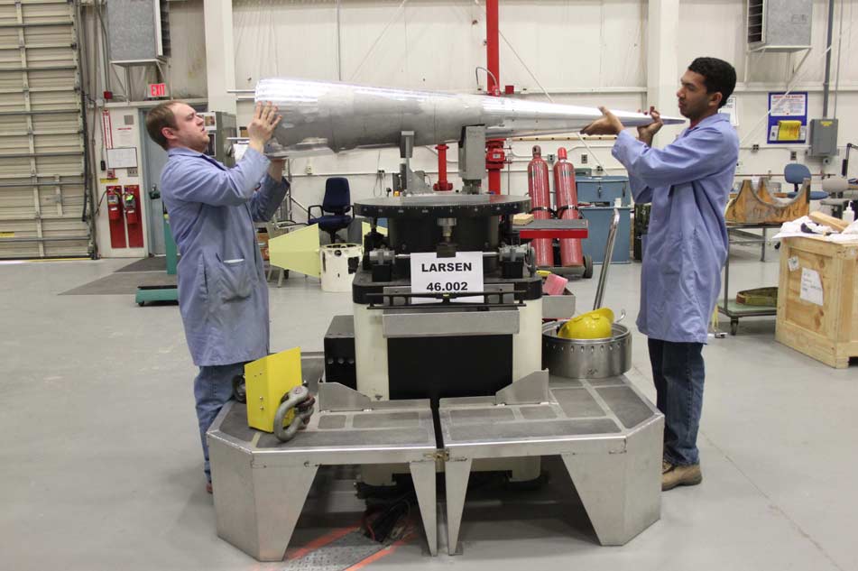
Mass Property Measurements
 Click on image to play video.
A payload’s mass properties – weight, center of gravity, and moments of inertia – are first calculated during the design phase. These numbers are incorporated into the early performance and attitude control system analyses to verify flight and control stability. Accurate mass property measurements of the launch and control configurations are used to confirm the theoretical (design phase) calculations and to provide the performance and attitude control system analysts with hard numbersto be used in the final pre-flight round of performance predictions.
Balancing – Static And Dynamic
Sounding rocket payloads must be balanced to function properly. Dynamic imbalances in the launch configuration could cause coning, which could decrease apogee and experiment data collection time. Static or dynamic imbalances in the control configuration could degrade the attitude control system’s ability to align property and acquire the mission target(s). The balance facility uses technology similar to that used for automobile tires but it is more accurate. Imbalances are first detected,then adjusted using lead or brass correction weights. Each payload has its own imbalance limits, determined by the launch, control, and mass property parameters specific to that payload.
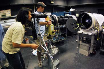


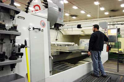
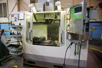
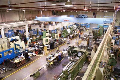 View of the sounding rockets machine shop.


Payload Systems
Several standard systems are available to be incorporated in a science payload. What systems are used depend on mission requirements, such as the need to recover the payload, payload attitude in space and data retrieval during flight. Some of the most common systems are described on this page.
Ogive Recovery System Assembly (ORSA)
Most telescope payloads are launched from sites with land impact areas and are recoverable. The O-give Recovery System Assembly (ORSA), which includes a parachute, is housed in the nose of the payload.

Attitude Control Systems
 Attitude Control Systems available for telescope and spectrometer payloads depend on the science target. A Celestial Attitude Control System (CACS) is used for studying stars, galaxies and other distant objects and a Solar Pointing Attitude Rocket Control System (SPARCS) is used for solar physics. Several different sensors such as, magnetometers, gyroscopes, solar/lunar sensors, and horizon sensors can provide input to the ACS.
This video shows the ACS jets firing in space. Click image to play.

 The Attitude Control System (ACS) frequently used for Geospace payloads utilizes sensor inputs from a magnetometer to align the payload with the Earth’s magnetic field. Small jets expell gas to rotate the payload in the desired direction. All three axes, pitch, yaw and roll can be controlled.
S19 Boost Guidance System
 The S19 is a boost guidance
system that keeps the vehicle
on a pre-programmed track
for the early portion of the
flight.
The S19 is a boost guidance
system that keeps the vehicle
on a pre-programmed track
for the early portion of the
flight.
Telemetry System
 The telemetry system transmits science and vehicle data to a ground station.
Experiments/Instruments
 The experiments or instruments are provided by the researcher, often from a University or Government agency, to collect data on the science target.
Astrophysics studies and geospace science missions are conducted using sounding rockets.
A frequently used instrument system for geospace science is a structure with deployable booms to measure ionospheric properites such as electric fields.
Astrophysics instruments include telecsopes and spectrometers to study objects near and far in the universe.
Experiment Testing Video: Boom Deployment
This video shows boom deployments on a geospace science payload. Booms are stowed inside the "skin" or outer shell of the payload during the upleg of the flight. Once in space the skin is removed and the booms are extended to start measuring scientific data. Click on image to play video.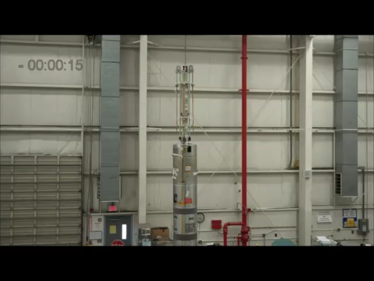
Experiment Testing Video: Sub-payload deployments
Small sub-payloads are frequently deployed from the main payload to extend the reach of the science mission. Deployment mechanisms, such as springs, gas springs or rocket motors, are tested prior to flight. The video shows sub-payloads from Dartmouth University deploying. Same video is shown in regular speed and then in slow motion. Click on image to play video.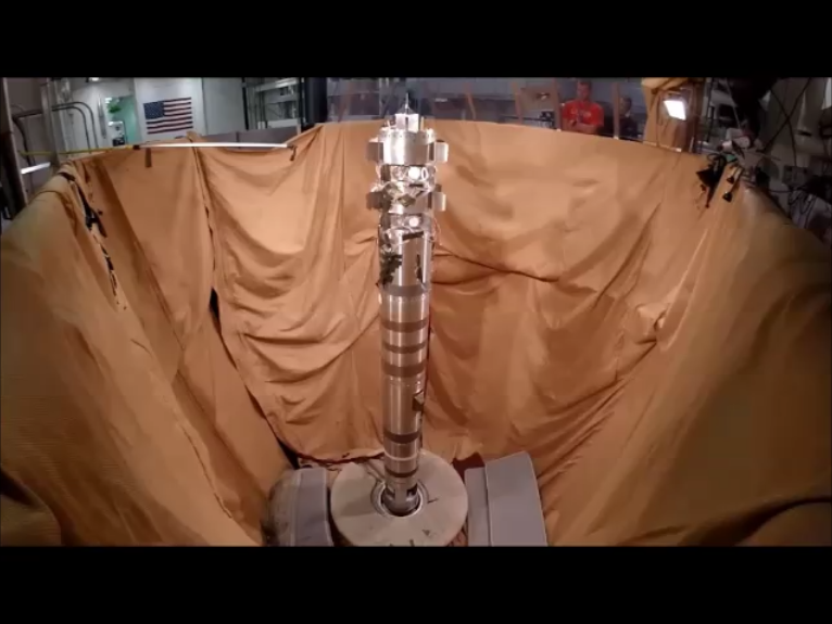
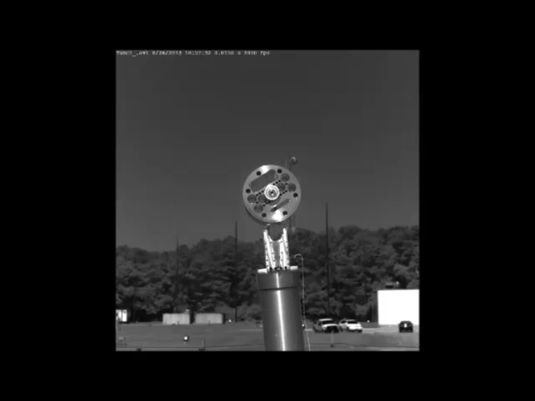
Experiment Testing Video: Sub-payload deployment
A different type of sub-payload deployment test is shown in this video. These sub-payloads were used with a gas spring deployment system developed specifically for the Auroral Spatial Structures Probe (ASSP) mission. The sub-payloads reached a velocity of 38 m/s (125 ft/s or 85 mph) in 0.028 seconds. The video shows high speed camera footage of ground testing of the system. Click on image to play video.
Shutter Door
 An electronically operated vacuum door that is opened in space allows the telescope/spectrometer to see the target. The door is closed prior to re-entry.
Aft Transition Section
 The aft transition section is used to mate two sections of different diameters. A crush bumper, to absorb energy at impact, is attached to the vacuum door and fits inside the transition section. The transition section also includes a system for separating the payload from the launch vehicle.